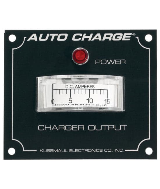
Kussmaul 20 Amp DC Meter
The Model IN-3-XX Indicator Panel contains an ammeter to indicate battery charger output current and a neon indicator to indicate power input to the vehicle
Available also in 20 or 25 Ammeter Current.
IN-3-15 (15 Amp)
IN-3-25 (25 Amp)
INSTALLATION INSTRUCTIONS
The Model IN-3-20 Indicator Panel contains an ammeter to indicate battery charger output
current and a neon indicator to indicate power input to the vehicle. The panel is designed to
cover a 2 1/2” hole in the vehicle.
To Mount the IN-3-20:
1. Locate a suitable spot on the vehicle and mark the center of the desired location.
2. Place the panel over the “center mark” so that the opening is precisely in the middle of the
rectangular opening.
3. Mark the location of the four corner holes.
4. Center-Punch the “center mark” and the four corner holes.
5. Drill out the center hole with a 2 1/2” hole saw and the four corner holes with a 5/32”
diameter drill.
6. Remove the protective laminate from the front of the panel and assemble the meter and
neon indicator to the panel.
7. Connect the neon indicator so that it is energized when power is applied to the vehicle
(see schematic).
Original: $54.95
-65%$54.95
$19.23Product Information
Product Information
Shipping & Returns
Shipping & Returns
Description
The Model IN-3-XX Indicator Panel contains an ammeter to indicate battery charger output current and a neon indicator to indicate power input to the vehicle
Available also in 20 or 25 Ammeter Current.
IN-3-15 (15 Amp)
IN-3-25 (25 Amp)
INSTALLATION INSTRUCTIONS
The Model IN-3-20 Indicator Panel contains an ammeter to indicate battery charger output
current and a neon indicator to indicate power input to the vehicle. The panel is designed to
cover a 2 1/2” hole in the vehicle.
To Mount the IN-3-20:
1. Locate a suitable spot on the vehicle and mark the center of the desired location.
2. Place the panel over the “center mark” so that the opening is precisely in the middle of the
rectangular opening.
3. Mark the location of the four corner holes.
4. Center-Punch the “center mark” and the four corner holes.
5. Drill out the center hole with a 2 1/2” hole saw and the four corner holes with a 5/32”
diameter drill.
6. Remove the protective laminate from the front of the panel and assemble the meter and
neon indicator to the panel.
7. Connect the neon indicator so that it is energized when power is applied to the vehicle
(see schematic).